This video documents a DIY attempt at building a custom gauge cluster (part two of the project). It covers designing and fabricating the face/pod, installing the electronics (microcontroller, drivers, and display/analog gauge movements), wiring sensors/CAN signals, and calibrating the readouts before final installation.
Build Sequence
1. Plan and design the cluster layout
Decide which gauges and digital elements to include, measure the mounting area, and create templates or 3D models for the faceplate and openings.
2. Fabricate the faceplate / bezel
Cut the panel material or 3D print the bezel, test-fit the gauges and display, and trim as necessary using a rotary tool, files, and sandpaper.
3. Prepare and mount displays/gauges
Mount the TFT/display and analog gauge movements into the faceplate, secure with hardware or adhesive, and ensure proper alignment and pointer clearance.
4. Assemble electronics and wiring harness
Wire the microcontroller, display, stepper/servo drivers, CAN adapter (if used), power and ground, and create a tidy harness with connectors and shrink tubing.
5. Program and calibrate the controller/software
Load the gauge software onto the microcontroller, map input pins/CAN messages to the correct gauges, and calibrate pointer ranges and digital readouts.
6. Install backlighting and finalize cosmetics
Install LED backlight strips and diffusion, paint or finish the face, and assemble the bezel for a clean look.
7. Bench test then vehicle install
Bench test all functions (power cycling, sensor signals, warning indicators) then remove the factory cluster or dashboard trim and install the custom cluster, reconnecting sensors or CAN as required.
8. Final calibration and verification
Drive/operate the vehicle (or simulate signals) to verify accurate readings, adjust software calibration if numbers/pointers are off, and check for fault codes or interference.
Frequently Asked Questions
How accurate will the gauges be compared to OEM?
Accuracy depends on the quality of signal inputs and calibration. Digital readouts can be very accurate if fed correct sensor/CAN data; analog pointer movements need careful calibration to match ranges.
VIEW FULL ARTICLE →Related Builds
 Basic dash build and small rewire of my 65 Mustang
 Part 2 of the solar mount project, 1/2 way done with help from a friend!
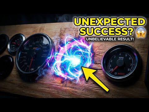 I Tried Making a Gauge Cluster and Didn't Expect This
 Running a tailgate reverse camera and an amp positive wire in a 2017 Chevy Silverado WT
 Light update for the garage!
 Successfully running an old UPS off solar!
Parts Used (8)
Used as the main digital display portion of the cluster; often drives speedo/tach readouts and warning indicators.
Runs the gauge software and interprets CAN or sensor inputs.
Used for tachometer, fuel/temp or other analog-style readouts.
If pulling speed/RPM from the vehicle CAN network.
General wiring supplies for harnessing the cluster.
Material cost for a printed bezel/panel; could be ABS/PLA depending on method.